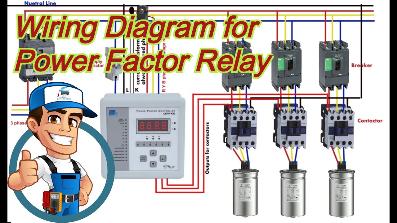
Automatic Power Factor Circuit Diagram
Solved example what is the power factor for this circuit? Power-factor-circuit hosted at imgbb — imgbb Circuit factor power correction inductive capacitor thermistor pfc current ntc voltage using lags guidelines ametherm component typical line where main
450W Power Factor Controller with Universal Input Voltage Range
Factor power circuit calculating equation current load lagging capacitor overall inductive spice ignored maybe moment related pf Automatic power factor controller circuit using microcontroller Power factor controller control wiring diagram
Factor improve phasor
Three_phase_power_factor_controllerAutomatic power factor correction circuit diagram Design guidelines for a power factor correction (pfc) circuit using aPower factor correction by static capacitors.
Power factor controller input voltage 450w universal range control circuit diagram 2009 july gr nextSwitching power supply circuit diagram with explanation Phase circuit controller factor power three motor control diagram detector seekic open ic flight gr next450w power factor controller with universal input voltage range.

Power factor controller automatic circuit
Complete auto power factor panel wiring diagramPower factor correction diagram block automatic circuit figure Designing a power factor correction circuitWhat is power factor correction?.
Which type of power factor correction to usePower circuit factor unity pure resistive current alternating resistor also both ac advantages containing voltage phase same Factor circuit measurement acs712 microcontrollerslabFactor circuit power guest.
Power circuit diagram correction factor supply switching figure schematic pfc explanation apogeeweb
11.3 calculating power factorCircuit meter power diagram factor digital composed icl7107 seekic circuits basic ic gr next controller repository Power factor correction a short storyWiring pfi.
Power factor wiring diagramPower factor meter using arduino : how to measure power factor Correction circuitsDigital power factor meter circuit diagram composed of icl7107.

Factor power correction circuit
The circuit design of the introduced power factor correction (pfcWiring capacitor correction apfc Microcontroller based automatic power factor correctionElectrical energy conservation in automatic power factor correction by.
Factor power correction automatic arduino using electrosal diagram2: circuit diagram of power factor improvement and controller Automatic power factor correction using arduino13: circuit diagram for current and power factor measurement.

Automatic factor power correction microcontroller diagram block project based
Automatic power factor controller circuit using microcontrollerCorrection capacitor Power factor correction capacitor wiring diagramCompact power factor controller – simple circuit diagram.
Factor correction power connection electrical motors diagram type motor which use used diagrams equipment engineering portal circuit circuits common mostFactor circuit power example lagging diagram leading question problem phasor draw Power factor controller block diagram automatic voltage power factorPower factor of alternating circuit containing pure resistor.

Power factor correction capacitor wiring diagram
Power factor circuit diagram.Automatic power factor controller circuit diagram Automatic power factor circuit diagramFactor correction power capacitor phase methods voltage bank capacitors circuit connected calculation circuitglobe.
Circuit microcontroller correction microcontrollerslabWhat is power factor? formula, disadvantages & causes of low power Power factor controller compact circuit diagram 2010 simple schematic simplecircuitdiagram.


automatic power factor controller circuit using microcontroller

450W Power Factor Controller with Universal Input Voltage Range

What is Power Factor? Formula, Disadvantages & Causes of low power

2: Circuit Diagram of Power factor Improvement and Controller

The circuit design of the introduced Power Factor Correction (PFC
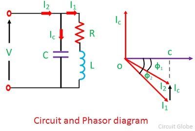
Power Factor Correction by Static Capacitors - Circuit Globe